
The Manchester Ship Canal is a 36-mile-long (58 km) inland waterway linking Manchester to the Irish Sea. The idea for a shipping lane to the inland town of Manchester came about because traders didn’t wish to continue paying Liverpool Docks and the railway companies to transport their goods to the city.
The rivers Mersey and Irwell were first made navigable in the early 18th century. Goods were also transported on the Runcorn extension of the Bridgewater Canal (from 1776) and the Liverpool and Manchester Railway (from 1830), but by the late 19th century the Mersey and Irwell Navigation had fallen into disrepair and was often unusable. In addition, Manchester’s business community viewed the charges imposed by Liverpool’s docks and the railway companies as excessive. A ship canal was therefore proposed to give ocean-going vessels direct access to Manchester. The region was suffering from the Long Depression; the canal’s proponents argued that the scheme would boost competition and create jobs. They built public support for the scheme, which was first presented to Parliament as a bill in 1882. Faced with stiff opposition from Liverpool, the canal’s supporters were unable to gain the necessary Act of Parliament to allow the scheme to go ahead until 1885.
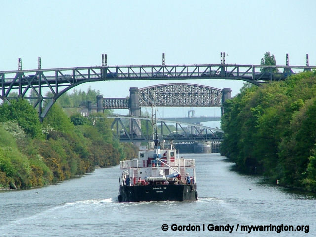
Manchester Ship Canal at Latchford
The idea that the rivers Mersey and Irwell should be made navigable from the Mersey Estuary in the west to Manchester in the east was first proposed in 1660 and revived in 1712 by the English civil engineer Thomas Steers. The necessary legislation was proposed in 1720, and the Act of Parliament for the navigation passed into law in 1721.
Construction began in 1724, undertaken by the Mersey & Irwell Navigation Company. By 1734 boats “of moderate size” were able to make the journey from quays near Water Street in Manchester to the Irish Sea, but the navigation was only suitable for small ships; during periods of low rainfall or when strong easterly winds held back the tide in the estuary, there was not always sufficient depth of water for a fully laden boat. The completion in 1776 of the Runcorn extension of the Bridgewater Canal, followed in 1830 by the opening of the Liverpool and Manchester Railway, intensified competition for the carriage of goods.
In 1844 ownership of the Mersey & Irwell Navigation was transferred to the Bridgewater Trustees, and in 1872 it was sold to The Bridgewater Navigation Company for £1.112 million. The navigation had by then fallen into disrepair, its owners preferring instead to maintain the more profitable canal; in 1882 the navigation was described as being “hopelessly choked with silt and filth”, and was closed to all but the smaller boats for 264 out of 311 working days.
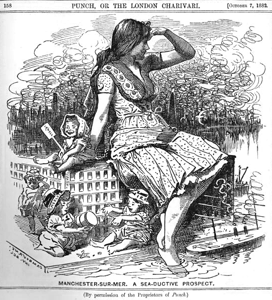
A cartoon in the satirical magazine Punch ridiculing the idea that Manchester could become a seaport to rival other major British cities such as Liverpool. A woman, representing Manchester, is dipping her toes into the proposed ship canal. The children playing around her represent the local waterways: the Irwell, Irk, Medlock, and Cornbrook. Edward Linley Sambourne (1844-1910). This work is in the public domain in its country of origin and other countries and areas where the copyright term is the author’s life plus 100 years or fewer.
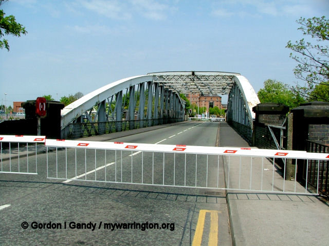
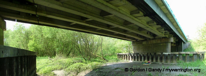
Rixton & Warburton bridge built c1894. There was a stone bridge over the old course of the River Mersey here. When the river was diverted to form part of the Manchester Ship Canal a steel bridge was built. It carries the B5159 from the A57 Manchester Road into Warburton village. The bridge still operates a toll, unless you are a pedestrian when it costs nothing. The old river bed can still be seen alongside (image, right).
Construction of the Manchester Ship Canal began in 1887. It took six years and cost £15 million (equivalent to about £1.65 billion in 2011).
Thomas Walker was appointed as a contractor, with Edward Leader Williams as chief engineer and designer and general manager. The 36-mile (58 km) route was divided into eight sections, with one engineer responsible for each. The first reached from Eastham to Ellesmere Port. Mount Manisty, a large mound of earth on a narrow stretch between the canal and the Mersey northwest of Ellesmere Port, was constructed from soil taken from the excavations. It and the adjacent Manisty Cutting were named after the engineer in charge. The last section built was the passage from Weston Point through the Runcorn Gap to Norton; the existing docks at Runcorn and Weston had to be kept operational until they could be connected to the completed western sections of the ship canal.
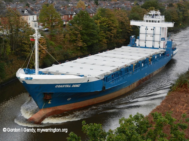
Coastal Deniz, built 1991, seen on 31 Oct 2013
It is still the longest river navigation canal and remains the world’s eighth-longest ship canal, only slightly shorter than the Panama Canal in Central America. More than 54 million cubic yards (41,000,000 m³) of material were excavated, about half as much as was removed during the building of the Suez Canal. An average of 12,000 workers were employed during construction, peaking at 17,000. Regular navvies were paid 4+1⁄2d per hour for a 10-hour working day, equivalent to about £16 per day in 2010. In terms of machinery, the project made use of more than 200 miles (320 km) of temporary rail track, 180 locomotives, more than 6000 trucks and wagons, 124 steam-powered cranes, 192 other steam engines, and 97 steam excavators. Major engineering landmarks of the scheme included the Barton Swing Aqueduct, the first swing aqueduct in the world, and a neighbouring swing bridge for road traffic at Barton, both of which are now Grade II* listed structures. In 1909 the canal’s depth was increased by 2 feet (0.61 m) to 28 feet (8.5 m), equalling that of the Suez Canal.
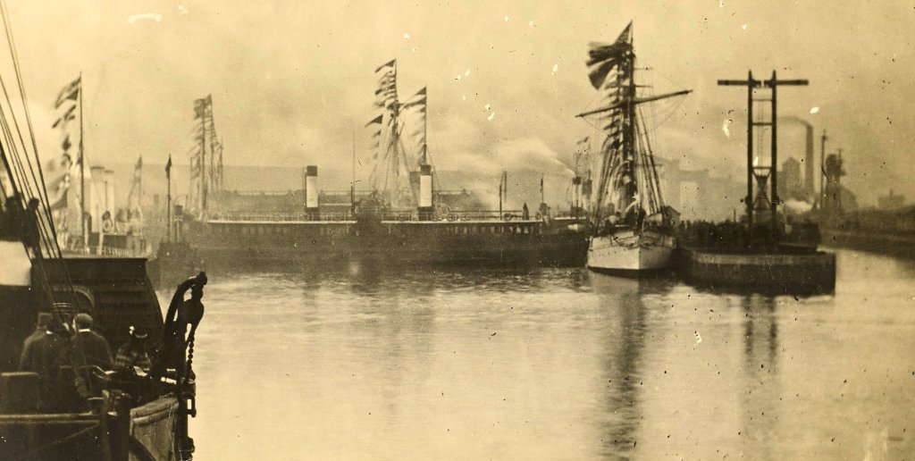
The Manchester Ship Canal enabled the newly created Port of Manchester to become Britain’s third-busiest port, despite the city being about 40 miles (64 km) inland. Since its opening in 1894, the canal has handled a wide range of ships and cargos, from coastal vessels to intra-European shipping and intercontinental cargo liners. The first vessel to unload its cargo on the opening day was the Pioneer, belonging to the Co-operative Wholesale Society (CWS), which was also the first vessel registered at Manchester; the CWS operated a weekly service to Rouen.
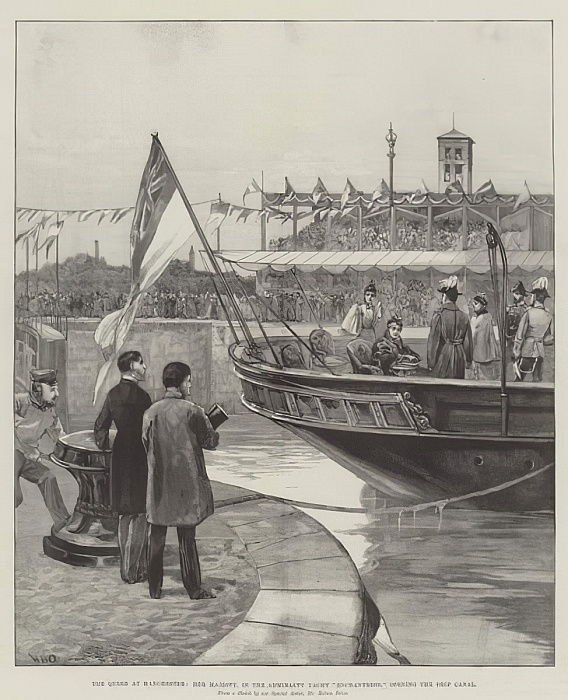
The Queen at Manchester, Her Majesty, in the Admiralty Yacht Enchantress, opening the Ship Canal, by William Heysham Overend. The author died in 1898, so this work is in the public domain in its country of origin where the copyright term is the author’s life plus 100 years or fewer.
Construction Photographs
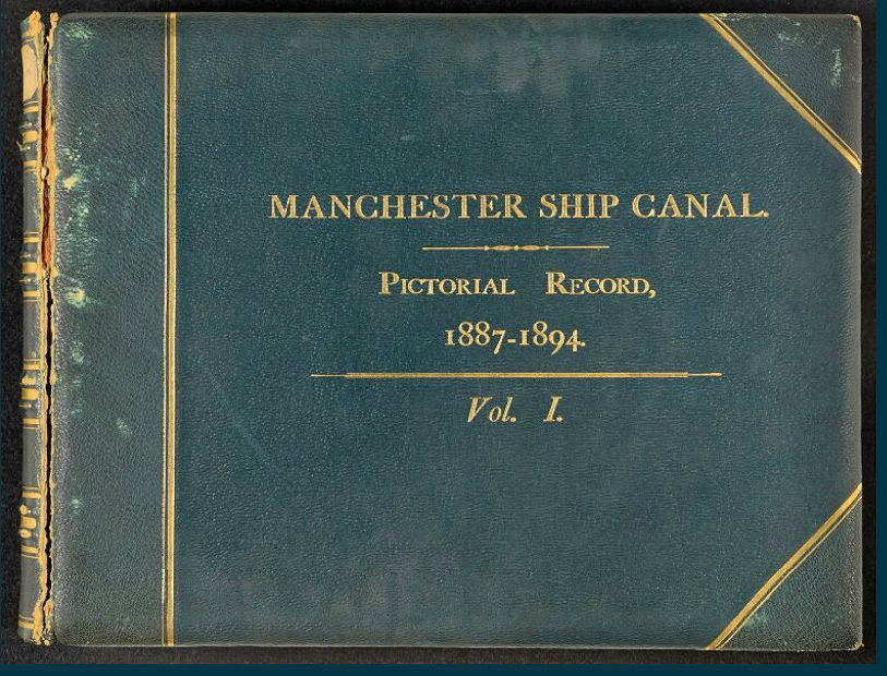
All images and text in this section are extracted from The Manchester Ship Canal: A Pictorial Record of its Construction, 11th November, 1887, to 1st January, 1894. Volume I. Latchford to Manchester by G. Herbert & Horace C. Bayley.
All images in this section are available for free download and may be used for any purpose under Getty’s Open Content Program. The text in this section is licensed under the Creative Commons Attribution 4.0 International License.
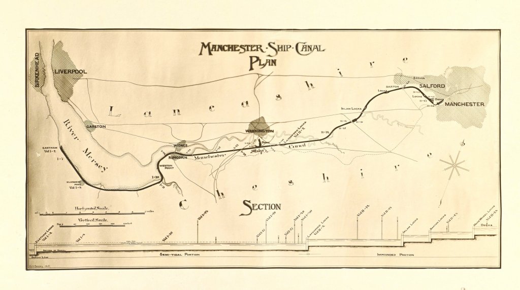
Key Plan of Line of Canal 1894
https://www.getty.edu/art/collection/object/108WCY
Moore Lane Swing Bridge – Exterior
There are in all seven swing road-bridges over the canal, and this, the second from the entrance, is fairly typical of the series. The turning point, it will be noticed, is not in the centre of the girder, but is 140 ft. from one end and 98 ft. from the other. This short end is loaded with pig iron under the road level, to balance the longer arm spanning the canal. The total weight is almost 800 tons, and this, moving on a circle of 64 rollers, is turned for either canal or road traffic by hydraulic power. The structure completes the quarter-revolution in rather less than one minute. The canal here is cut through sandstone which rises almost to the water level, and the sides are consequently almost vertical; the earth above is dressed back to a flatter slope and pitched with rough stone.
Acton Grange Railway Viaduct
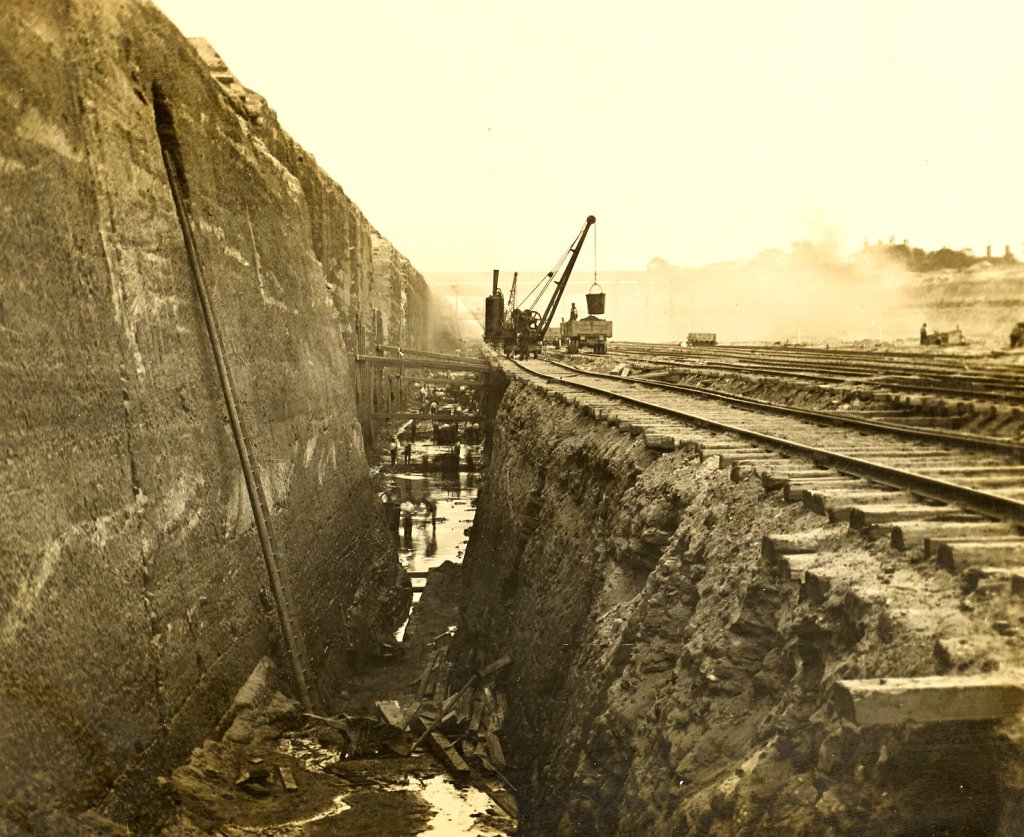
This bridge carries the London and North Western main lines from the North to both Chester and Crewe. The main girders were constructed on a timber scaffold, which has subsequently been removed, and the rock under the bridge is here being removed. The work is of necessity slow, as the rock has first to be shaken by blasting cartridges, and then the detached lumps are lifted by steam cranes into trucks. The wagons to the right are on the finished bottom of the canal and stand more than 110 ft. below the underside of the bridge girders. The crossing of the railway at this point makes a very oblique angle with the line of the Canal, and the bridge is consequently very much longer in span than if it were carried square across.
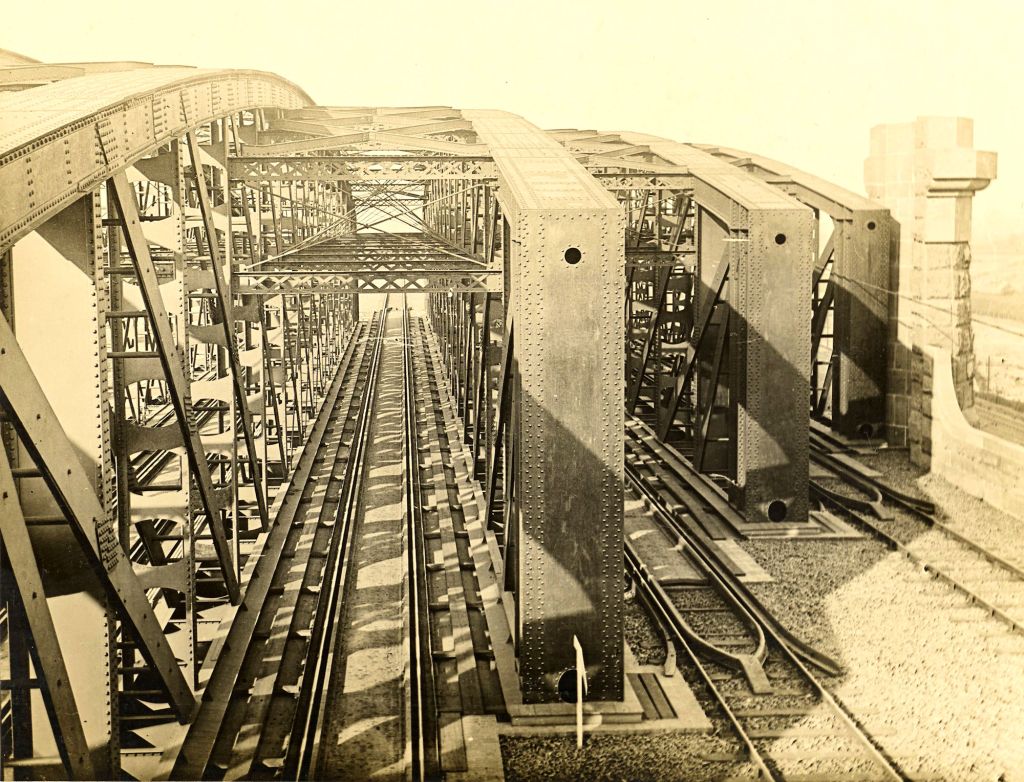
Acton Grange Railway Viaduct Interior
This photo is taken from the railway signal cabin spanning the track. The two lines on the right are reserved for Chester traffic and the remaining two used for Crewe trains. In designing the flooring and permanent way over the viaduct, a special form of trough for carrying the rails has been contrived so that should a train unfortunately leave the metals it would simply run in the trough instead of on the rail, and it would neither overturn nor touch the girders.
Acton Grange Railway Viaduct Wind Bracing
The construction of the main girders is depicted in this photograph, taken from the top of one of the abutments. The interlacing of the various members is apparently very confusing, but a careful study of this page will convey a slight idea of the vast amount of work in structures of this kind. The rounding of the girder tops should be noticed, and it must be remembered that the view is taken obliquely, looking through four of the main girders.
Stockton Heath – Cutting under Swing Bridge
The Swing Bridge shown here carries the Warrington and Northwich main road over the canal. Under the left span of the truss is seen the lock forming the junction of the Old Quay Canal with the new waterway. The short length of this canal between here and Howley Quay, above Warrington, is all that now remains of this old navigation, which formerly connected with the Mersey at Runcorn. It is interesting to note the great difference in depth between these two waterways; although the rock sill forming the entrance to the side lock apparently rises so high above the bottom of the Ship Canal, still there is ample draught for barge traffic, even at low tide. This photograph was taken from the bed of the canal, immediately before the water was admitted.
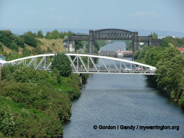
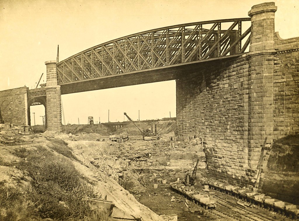
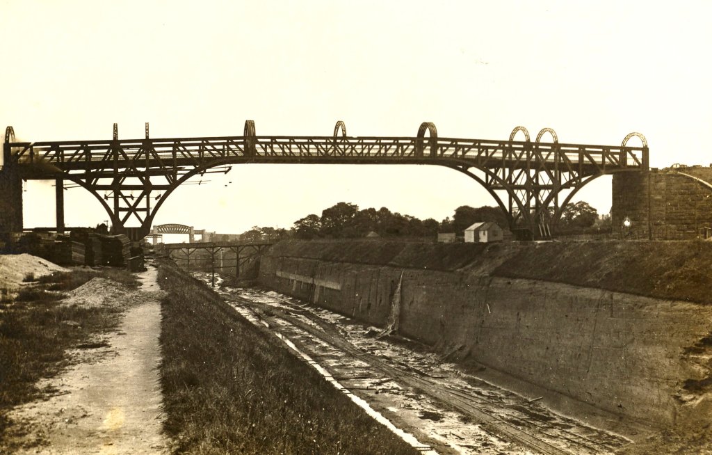
Latchford – Cantilever Bridge over Canal
Of the nine road bridges over the canal, only two are at such a height above water level as to render fixed structures possible. These two, the one at Latchford and the other at Warburton, are identical in design, and both give a clear headway of 75 feet above ordinary water line. As in the case of the great bridge over the Firth of Forth, the cantilever principle has been adopted, thus obviating the necessity for heavy temporary staging during construction, besides considerably reducing the actual weight of the structure. This photograph shows the Latchford Bridge in its finished state, the method of erection being more fully shown in the bridge at Warburton (see next photo).
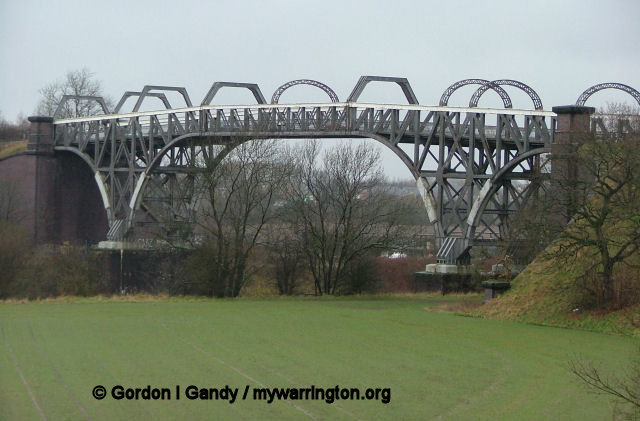
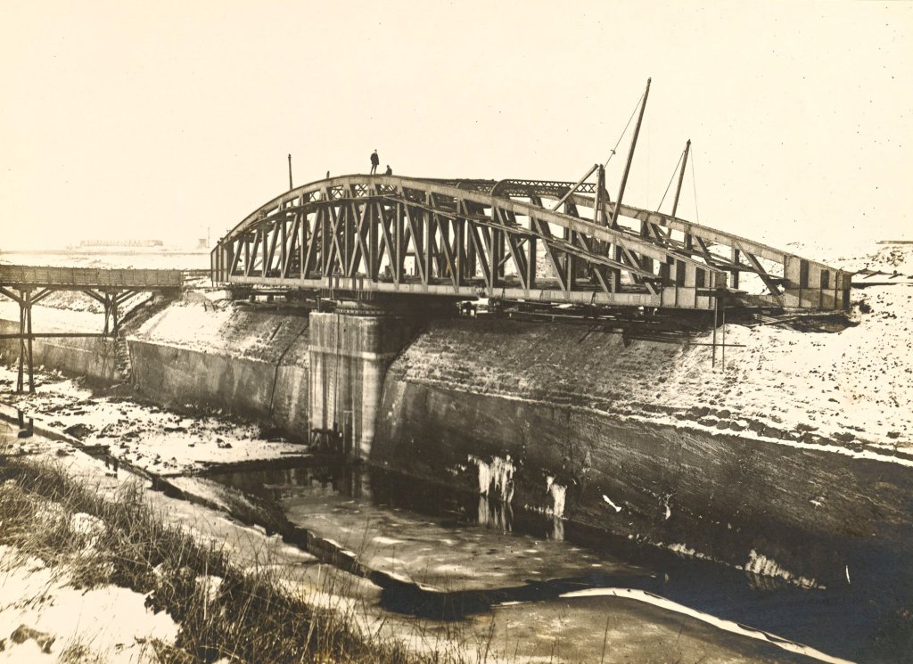
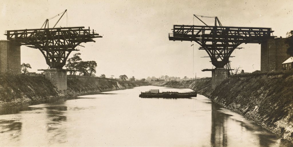
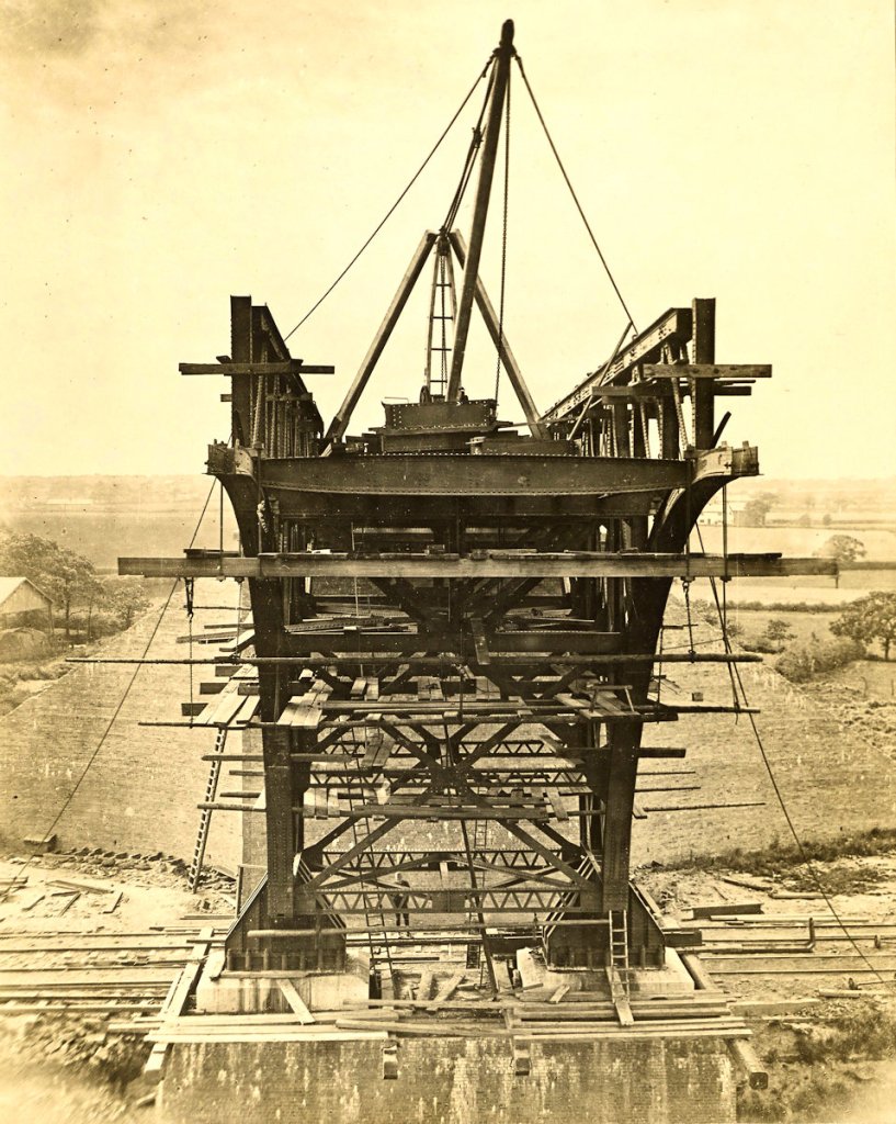
Warburton – High Level Road Bridge
This is the second fixed road bridge over the canal and is identical in design with the one at Latchford, shown in its finished state above. The present view was secured when the bridge was about half completed and shows very clearly the great advantage of this form of structure. It will be noticed that the bridge is being erected after the cutting has been filled with water, and further, that no temporary staging is needed. The brick and concrete foundations having been built up from below the bed of the canal, the steel framing is commenced. By constructing the arms or cantilevers symmetrically, as here shown, the work remains balanced on its somewhat narrow base. The shore-ends of the two cantilevers are afterwards secured below road level, in order to counterbalance the weight of the girders connecting the arms extended over the water. These independent girders are put together on pontoons and hoisted into position by the two derrick cranes shown in the photograph.
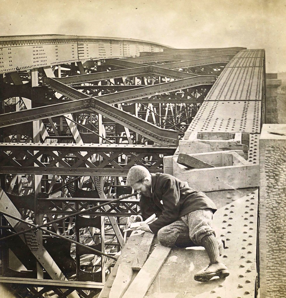
Warburton – High Level Road Bridge North Cantilever
A more detailed view of the construction of the bridge is here given, in a photograph taken from the rivetters’ stage hanging from the underside of the opposite cantilever. Some idea of the great height of this road above the water may be gathered by a comparison with the farm buildings and trees seen on either side of the wing-walls of the abutment.
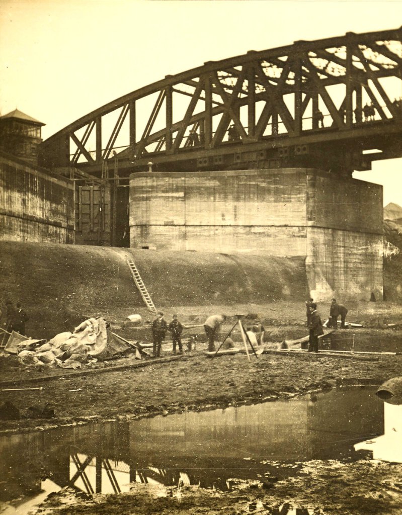
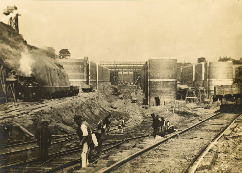
Latchford – Cutting for Locks
These locks are situated 21 miles up the canal from Eastham, or 14 1/2 miles from Manchester, and form the head of the semi-tidal portion of the work. As in the case of Eastham, the deep cutting here is for the footings of the concrete lock wall, and the solid rock on the right will subsequently have to be removed to form the lock basin.
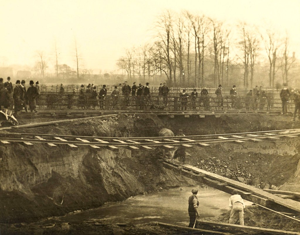
Latchford – Effects of the Great Flood
The general flooding of the cuttings early in November proved to be the most serious misadventure experienced during the whole construction of the works. On the Latchford section, a sudden spate in the River Dane at Lymm caused the destruction of a temporary dam, thus admitting the Mersey, itself in flood, and laying about five miles of half-finished cutting under thirty feet of water. Early in the previous summer a tunnel had been driven underneath the Warrington and Stockport Railway at Latchford, to admit the passage of spoil wagons from one cutting to the other. The rush of the flood waters through this heading washed away a considerable portion of its roof and undermined the North Western Line. This view, taken on the day of the accident, looking down stream, shows the remarkable condition in which the contractor’s railway was left, festooned across the gap caused by the collapse of the tunnel.
Latchford – Locks
The lock walls are now practically complete, and the gates are being constructed in position. The serious flood in the previous November at this point, while sadly delaying the work, fortunately did no damage to the permanent structure.
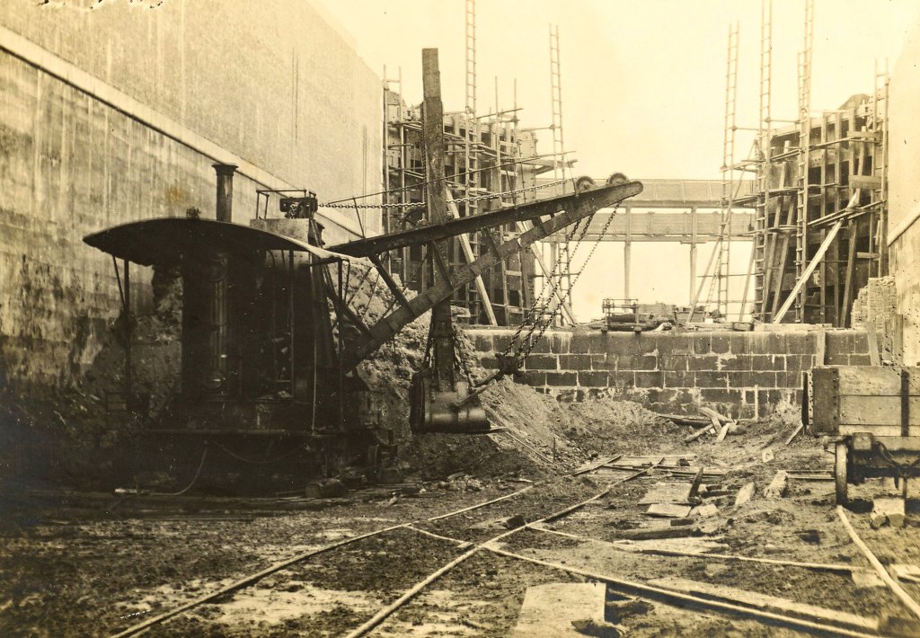
Latchford – Interior of Large Lock
Once the concrete walls had been built in the trenches, the solid core had next to be removed, so that the concrete floor of the lock chamber might be laid. The present view shows a steam navy at work removing the last of this rock into tip-waggons. The railways seen here , as also throughout the work, are the ordinary standard gauge of 4 ft. 8 1/2 in. The stone wall across the head of the lock forms the lift at this point, and rises 16 1/2 feet above the lock bottom, corresponding with the difference in water level between the upper and lower ponds. The head gates are almost completed, and the lock walls built up to their full height. The double bridge in the background is a temporary structure, carrying a farm road and a watercourse across the cutting.
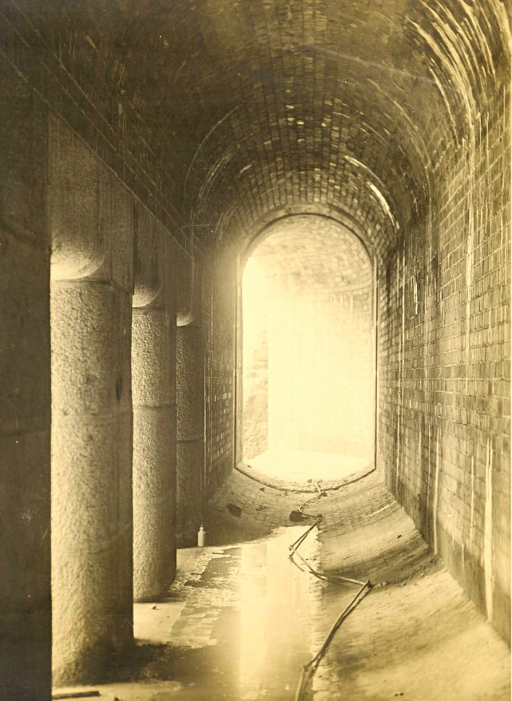
Latchford – Interior of Sluice Culvert
The filling and emptying of these great locks is effected by sluice-ways formed in the solid concrete wall on either side of the chamber. These culverts for the 60 ft. locks measure 12 ft. by 6 ft., and when in use will be 14 ft. under water. The openings on the left in the photograph are into the lock chamber, immediately behind the lower gates. The open end beyond discharges into the lower reach of the canal and allows the escape of water when vessels are being lowered. The flow of water is controlled by an iron sluice gate, working in the groove seen at the bend of the culvert.
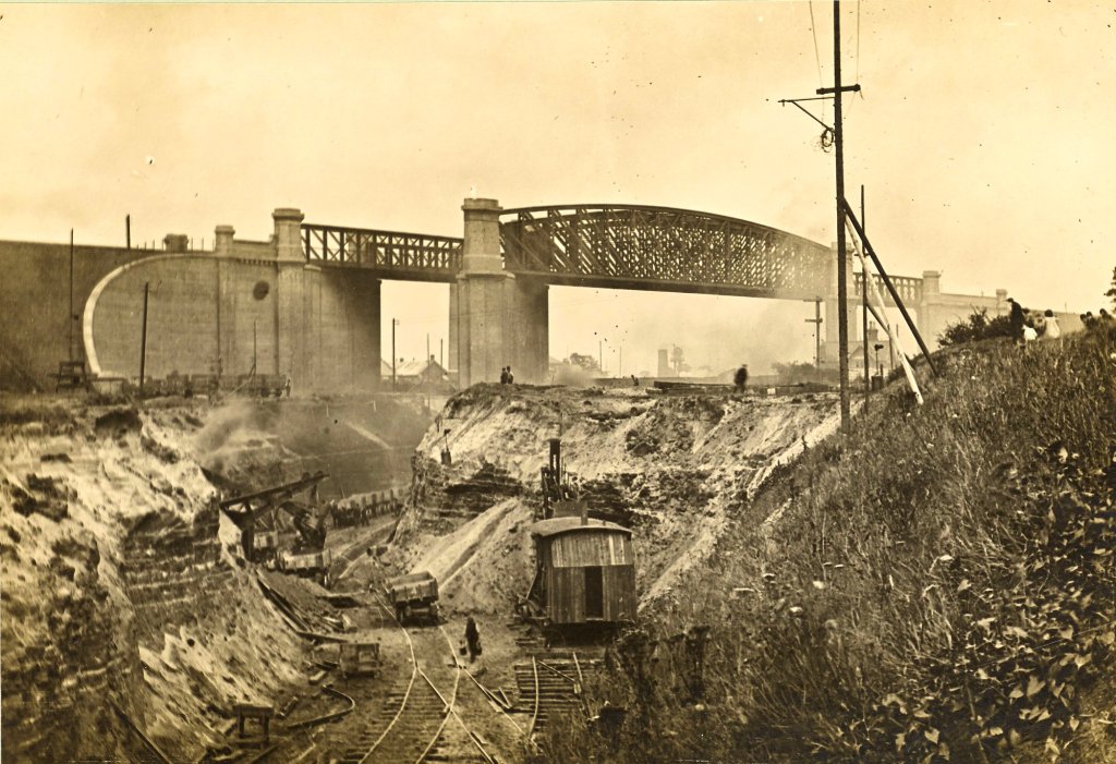
Latchford – High Level Railway Viaduct
The general design of this viaduct, which carries the Warrington and Stockport branch of the L. & N. W. Railway over the canal, is similar to that at Acton Grange seen earlier. The steam navvies in the foreground are at work cutting through the old railway track, which obviously could not be touched until all traffic had been diverted over the new viaduct. The railway signal and crossing-keeper’s house indicate the position of the old line. The several railways crossing the line of work formed the last serious barriers to the completion of the canal; and when at last possession was obtained, the work of cutting through them was continued day and night, without interruption, by the aid of electric and oil spray lights.
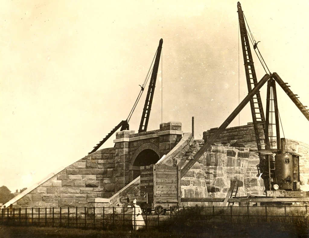
Latchford – Bridge under Railway Deviation
The mode of constructing heavy masonry bridges on the railway deviation works is here shown. The foundation having been laid, the abutments and wing-walls are carried up by means of the two large cranes; and when all is safely arched over, the tip head is carried across the new work, and the embankment pushed forward to join the old track. Following the practice of the L. & N. W. Railway Company, the abutments in this and other bridges on their system have been built in sandstone, with arches turned in blue brick. But on the Cheshire Lines deviations the exact converse has been adopted, the abutments being in brick and the arches in stone.
Latchford – Locks: Scene at Opening
This view was taken from the deck of the “America,” just before the departure of the “Norseman.” The yacht, with her top masts lowered, is lying above the 45 ft. lock, in which are the “Snowdrop” and the “Great Britain,” while the “Crocus” is seen broadside on in the storm byewash, together with the remainder of the flotilla. Behind, the Latchford High Level Railway Bridge rises dimly through the steam and haze.
THE MSC Railway
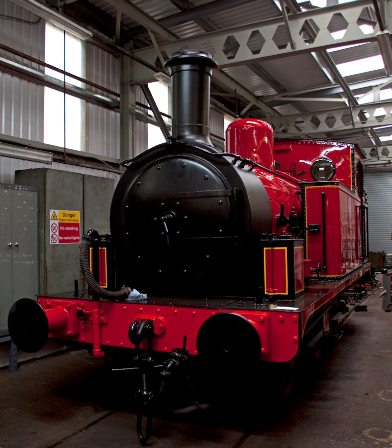
To service the large amount of freight being landed at the canal’s docks, the MSC Railway was created to carry goods and connect to the various railway companies near the canal. The MSC Railway, unlike other railway companies in the UK, was not nationalised and became the largest private railway in the UK during the British Railways era. The MSC Railway operated a large fleet of steam locomotives, many of which were 0-6-0 tank engines.
The image, right, shows the preserved Manchester Ship Canal Railway 0-6-0T locomotive, number 686 The Lady Armaghdale, now on display at The Engine House in Highley. Author: Tony Hisgett from Birmingham, UK. This file is licensed under the Creative Commons Attribution 2.0 Generic license.
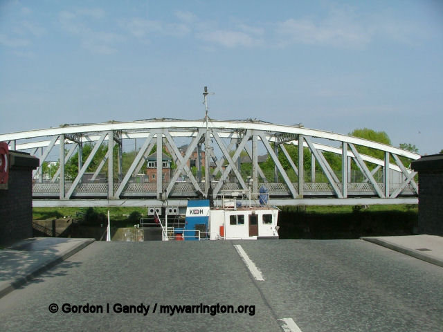
Swing bridge in action.

The amount of freight carried by the canal peaked in 1958 at 18 million long tons (20 million short tons), but the increasing size of ocean-going ships and the port’s failure to introduce modern freight-handling methods resulted in that headline figure dropping steadily, and the closure of the docks in Salford in 1984.
In 1984 Salford City Council used a derelict land grant to purchase the docks at Salford from the Ship Canal Company, rebranding the area as Salford Quays. Principal developers Urban Waterside began redevelopment work the following year, by which time traffic on the canal’s upper reaches had declined to such an extent that its owners considered closing it above Runcorn. In 1993 the Ship Canal Company was acquired by Peel Holdings.
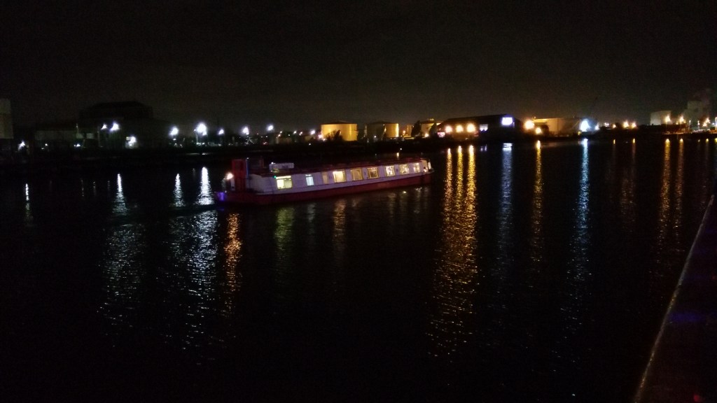
Pleasure boat at Salford Quays on 15 Dec 2016
Unlike most British canals, the MSC and the Bridgewater Canal were never nationalised, and remain in the ownership of the Manchester Ship Canal Company, a subsidiary of Peel Holdings.
To conclude my story, here are a series of photos from along the Manchester Ship Canal.
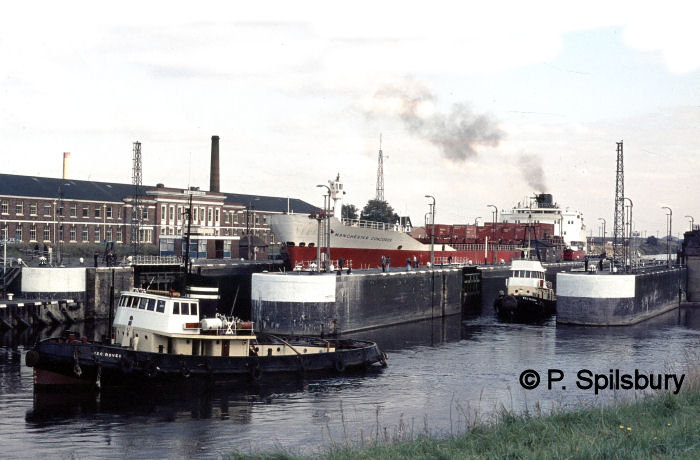
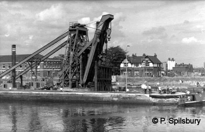
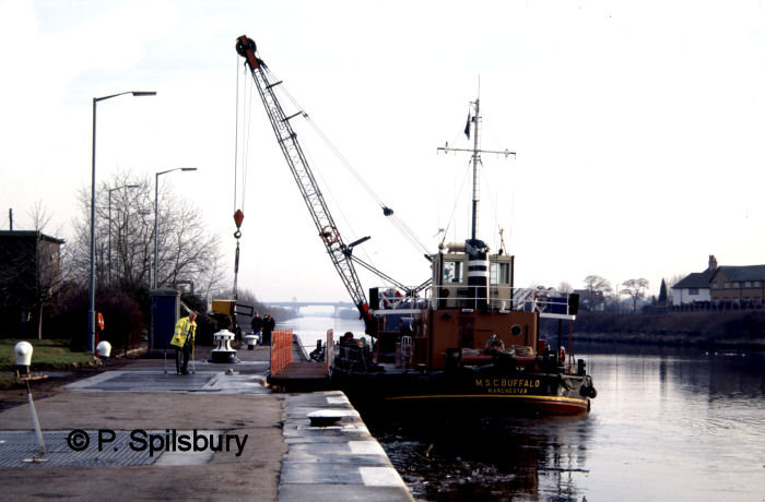
We’ll start with three images by Peter Spilsbury show scenes at Latchford Locks.
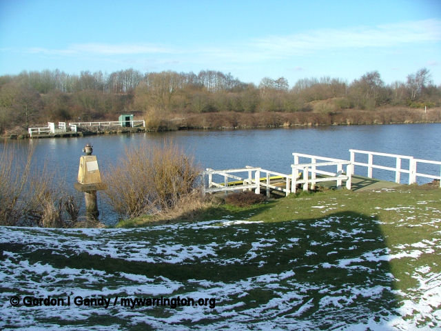
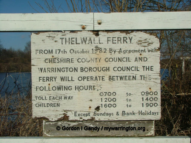
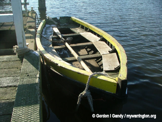
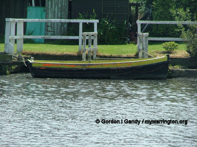
Thelwall Ferry
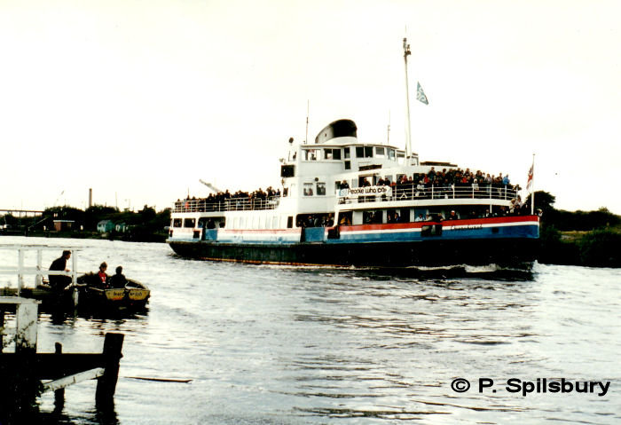
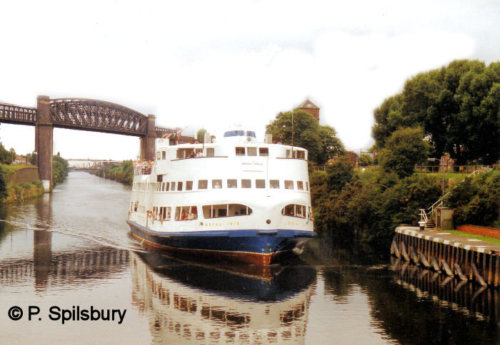
Because the route of the Manchester Ship Canal cut through an ancient right of way, the Manchester Ship Canal Company is bound by an Act of Parliament to provide the ferry service. This is in the form of a ferry, as seen in the photos below. The wooden rowing boat has since been replaced by a stainless steel version. The final photo of the set shows The Royal Iris passes by Thelwall Ferry on 2 August 1984 in a photo by Peter Spilsbury.
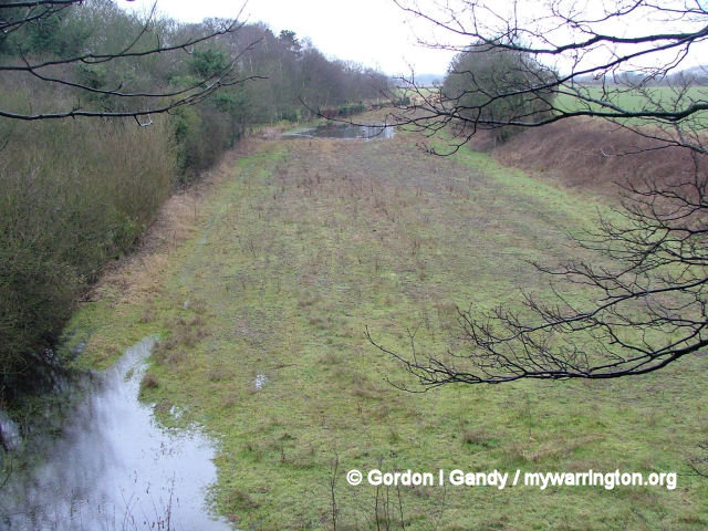
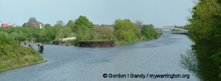
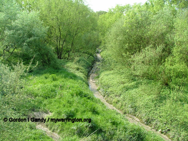
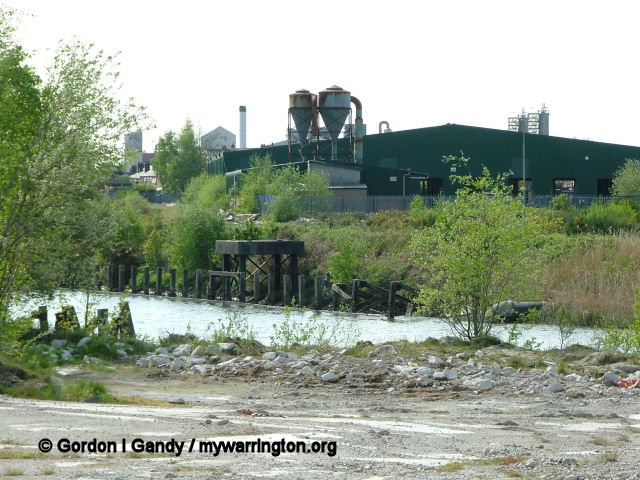
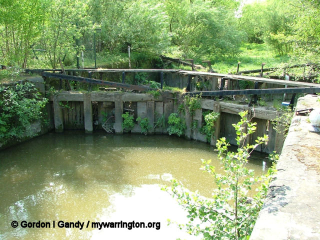
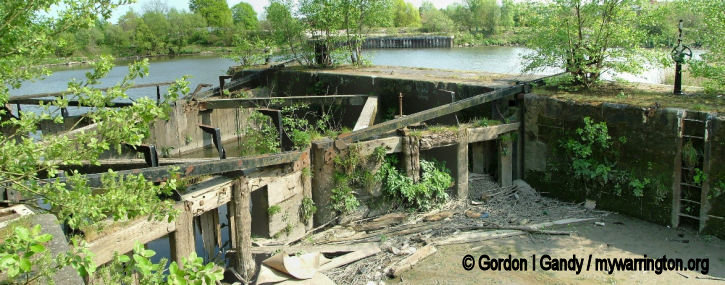
Walton Lock
Walton Lock is an area linking the Manchester Ship Canal with the Mersey. The link is now disused and mostly dried up.
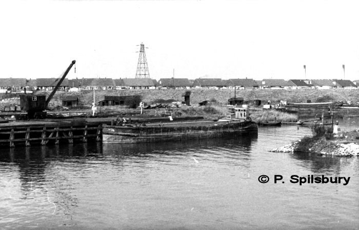
The remains of the lock today.
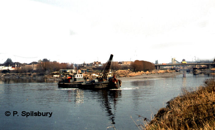
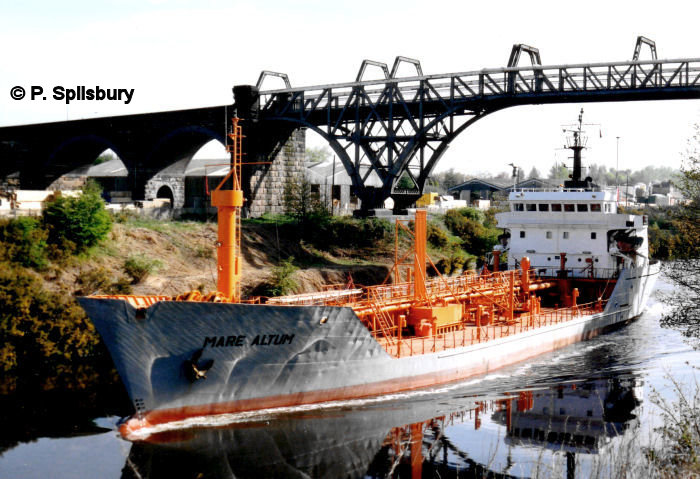
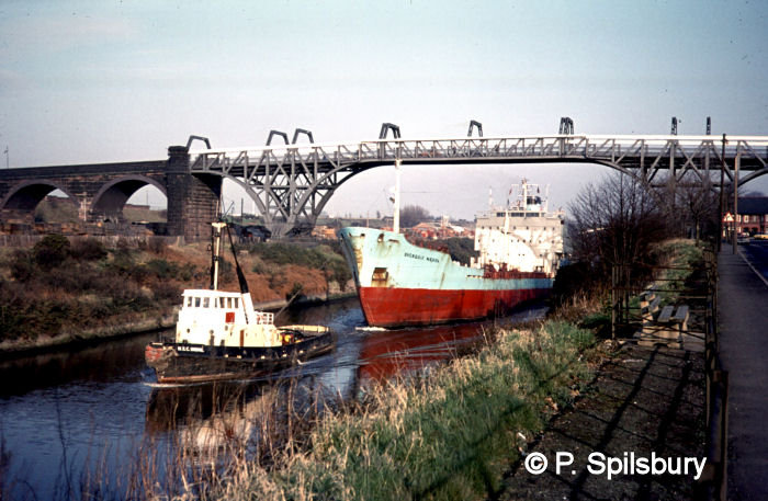
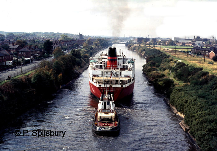
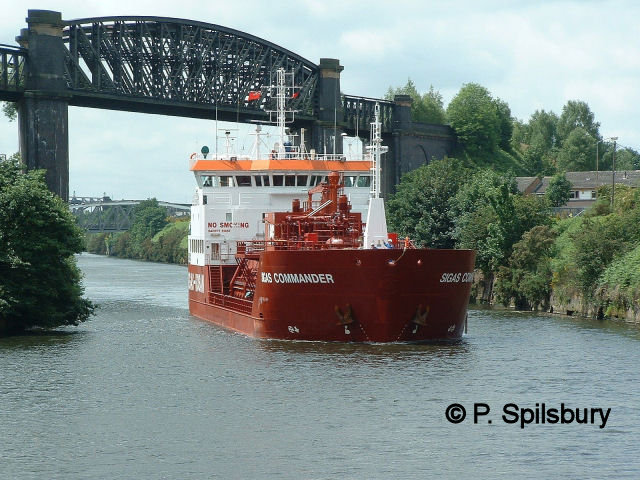
More images along the Ship Canal, taken by Peter Spilsbury
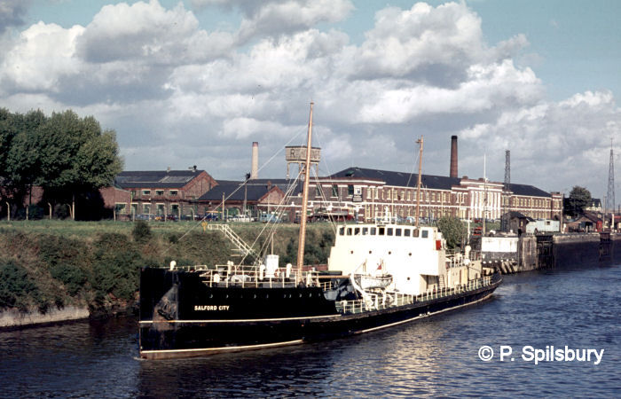
Manchester’s sewage was treated at Barton and shipped out to the Mersey Bar by a number of vessels over the years until a new treatment plant was constructed at Waterloo Dock, Liverpool by North West Water (later United Utilities). Salford City is seen here at Latchford Locks with Richmonds factory behind. Photo © P Spilsbury
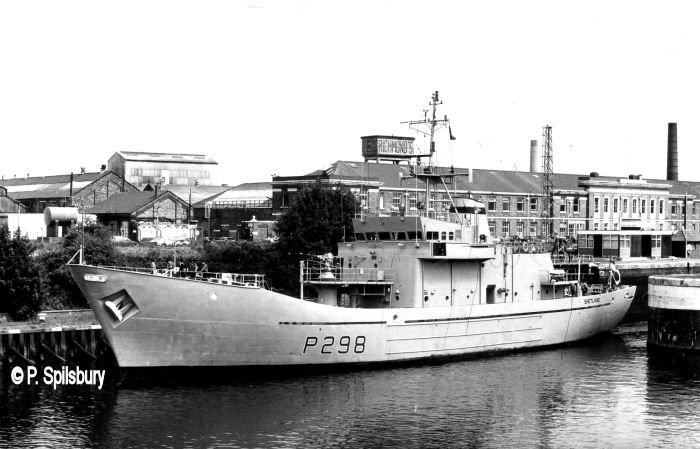
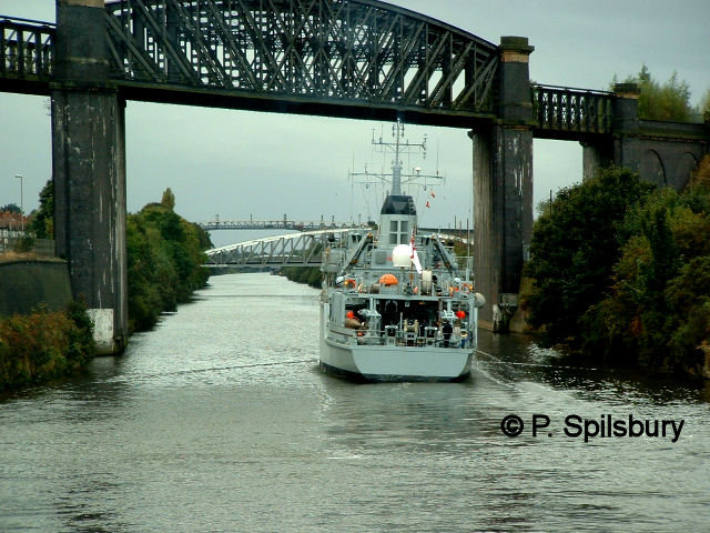
HMS Shetland is an Island class patrol vehicle seen here at Latchford Locks with
Richmonds cooker factory behind (later New World before it closed) Photo 24 Jun 1981
And finally…
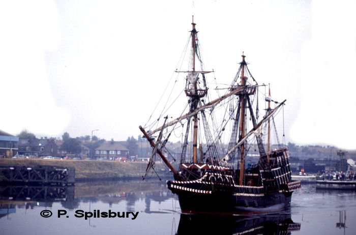
The replica Golden Hind passes through Latchford on a visit to Salford Quays on 25 October 1991. The original was the ship in which (Sir) Francis Drake circumnavigated the globe in 1577-80. Originally called the Pelican, it was renamed by Drake in mid-voyage in 1577, as he prepared to enter the straits of Magellan. It was renamed in honour of his patron, Sir Christopher Hatton (1540-91), whose armorial crest was a golden hind (the heraldic term for a female deer). Photo Copyright © P Spilsbury
Some information from Wikipedia
