
The North Wales Coast Line is the railway from Crewe on the West Coast Main Line and Chester to Holyhead on the Isle of Anglesey. Warrington’s connection is included here because the modern route includes the Manchester to Llandudno and Holyhead section via Chester.
The line contains several notable engineering structures, namely Conwy railway bridge across the River Conwy, and Britannia Bridge across the Menai Strait. It also includes the station with the longest name in the world. You know the one.

But what does all that mean?
The long Welsh railway station and village name is often shorted to Llanfair P.G. these days. The translation of the full-length word is:
“St Mary’s church near the pool of the white hazel near the fierce whirlpool and St Tysilio’s church by the red cave”.
However, the original name of the village is Llanfairpwllgwyngyll. It was lengthened by a nineteenth century publican who thought it might entice more of the many visitors to the attractions of Snowdonia to cross into Anglesey if he “enhanced” the name to a record length. Hence its current long-winded modification. For the original village name translation, stop after “white hazel”. My thanks to Mike who supplied the additional information.
Llanfair P.G. station on 20 June 2025
The first section of line from Crewe to Chester was built by the Chester and Crewe Railway. The line was 21 miles (34 km) in length, the engineer was Robert Stephenson and the contractor for the work was Thomas Brassey. absorbed by the Grand Junction Railway shortly before opening in 1840.
The remainder was built between 1844 and 1850 by the Chester and Holyhead Railway Company as the route of the Irish Mail services to Dublin. It relied on the co-operation of other railways to reach London and in 1859 it was absorbed by the London and North Western Railway.
Between Chester and Saltney Junction, the line was, from the start, used by trains of the Shrewsbury and Chester Railway The engineer for the line was Henry Robertson, a partner in locomotive builders Beyer Peacock, while the contractor was Thomas Brassey in partnership with William Mackenzie and Robert Stephenson. It was later incorporated in the Great Western Railway.
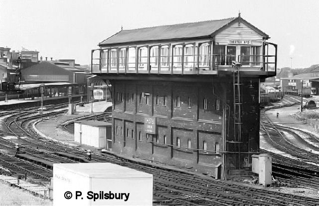
Chester No 2 signal box on 2 Aug 1981. Photo © P. Spilsbury
Reader Story: In 2003 when on holiday in Porthmadog, I actually rode on the footplate of an engine on the Welsh Highland Railway. They had an ‘open day’ where for £5 (adults only) you could ride the length of the track and back – it was just brilliant. The heat, the smoke and smell. HEAVEN. I even got to pull the cord and toot the hooter. A DREAM COME TRUE. Anon.
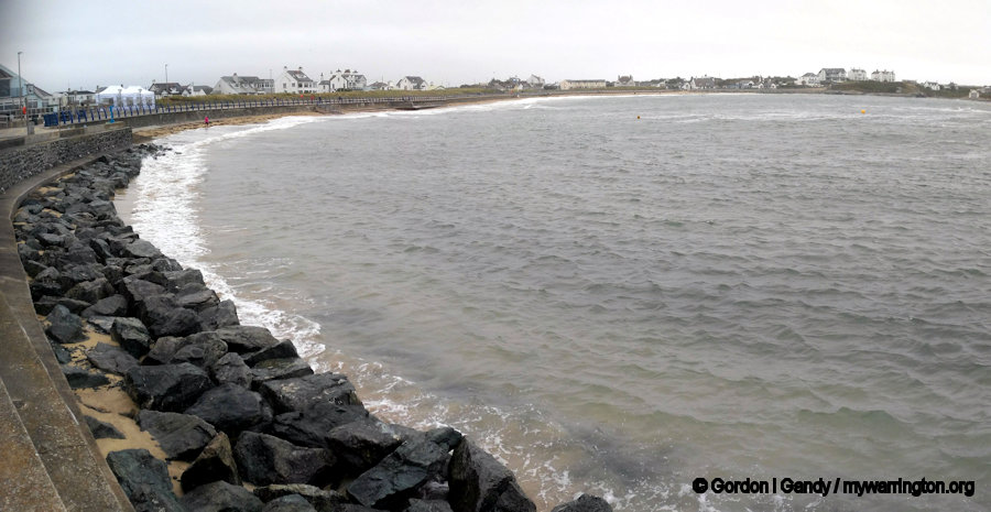
So important was the line in the 19th and early 20th centuries to passenger, mail and freight traffic between Britain and Ireland that the world’s first experimental and operational water troughs were installed at Mochdre between Colwyn Bay and Llandudno Junction. Their purpose was to enable steam engines (especially on the Irish Mail) to collect water without stopping. Later, considerable stretches of line between Chester and Colwyn Bay were quadrupled to increase line capacity but these sections have now been reduced to two tracks.
Principal through passenger services are London Euston to Holyhead, Bangor, Chester and Wrexham General operated by Avanti West Coast and Crewe to Holyhead, Cardiff to Holyhead and Manchester to Llandudno currently operated by Transport for Wales Rail. The line still provides the UK railway part of the through passenger service to Dublin using fast car ferries from Holyhead to Dublin Ferryport.
BR 73157 at Moore Troughs. The troughs enabled water to be picked up by a scoop as the train travelled along the track to save time at stations. Who can forget The Royal Train episode of Dad’s Army?
Photo © P. Spilsbury.
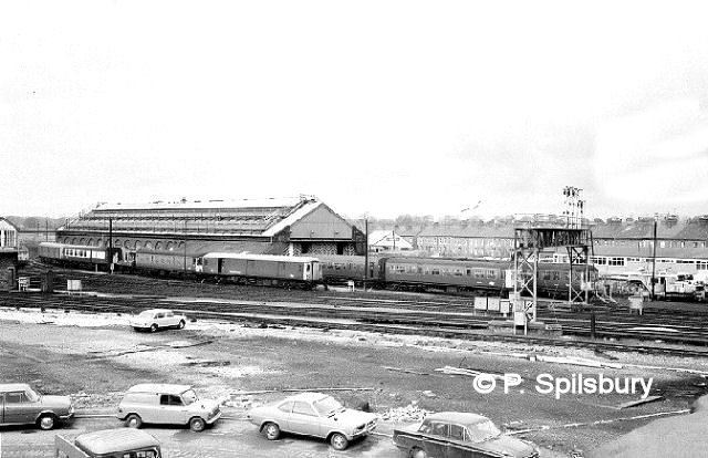
Chester Motive Power Depot (MPD). Photo © P. Spilsbury.
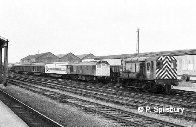
25076 and 08665 at Chester Station on 10 Sep 1984. Photo © P. Spilsbury.
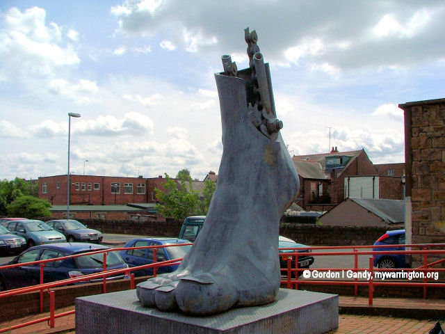
Big Foot outside Flint Station. Photo © GI Gandy, mywarrington.
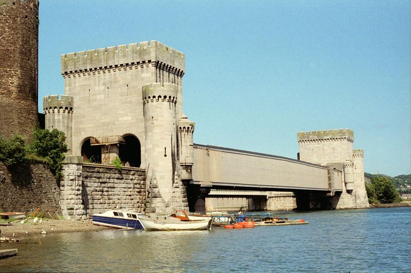
Conwy Railway Bridge
The Conwy Railway Bridge carries the North Wales coast railway line across the River Conwy between Llandudno Junction and the town of Conwy. The wrought iron tubular bridge, which is now Grade I listed, was built in the 19th century. It is the last surviving example of this type of design by Stephenson after the original Britannia Bridge across the Menai Strait was destroyed in a fire in 1970 and replaced by a two-tier truss arch bridge design.
During the 1840s, the Chester and Holyhead Railway committed to building a railway line along the coastline of North Wales between Chester and Holyhead on Anglesey.
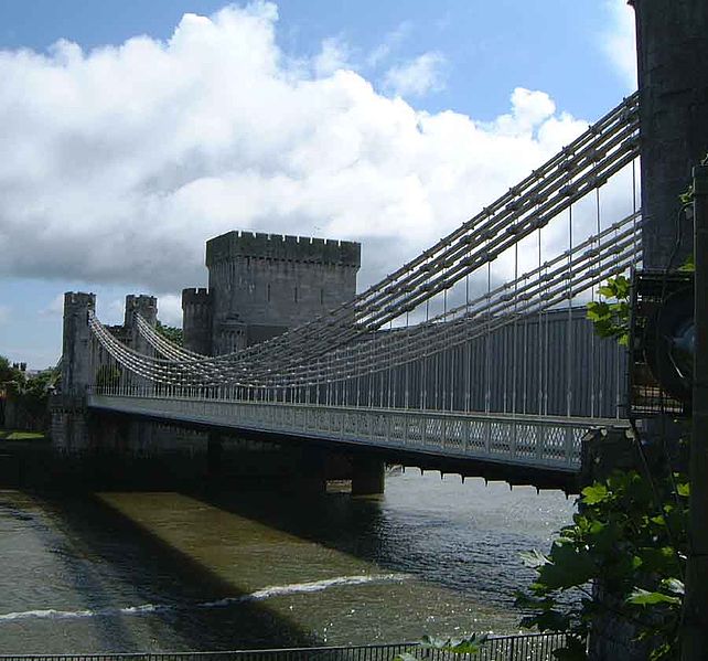
The route necessitated crossing the River Conwy alongside the existing Conwy Suspension Bridge, built two decades earlier by Thomas Telford. Initially a suspension bridge was considered, but its inherent flexibility posed challenges to rail traffic.
Robert Stephenson the chief engineer of the Chester and Holyhead Railway designed the bridge. He devised a tunnel-like rigid tube which would be suspended above the Conwy to accommodate tracks inside it. The box-section tube possessed sufficient rigidity to be self-supporting over the span of the river.
Conway Tubular Bridge. Image by Joost J. Bakker is used under Creative Commons licence.
While developing the design which was made of wrought iron, Stephenson consulted William Fairbairn (who had extensive experience in working with iron), the mathematician Eaton Hodgkinson and resident engineer Edwin Clark.
During February 1846, the men presented their design to the railway company who approved further development and experimentation to validate the design.
Several different cross sections were built including a one-sixteenth scale model of the Britannia Bridge, 23.8 meters in length fitted with a rectangular-section tube. Testing incorporated various conditions, including wind and temperature variations.
The designs for both the Conwy Railway Bridge and Britannia Bridge were similar.

Conway [road] Bridge c.1840, before the construction of Stephenson’s tubular bridge. Image used under Creative Commons licence.
Construction
During May 1846, groundwork for the bridge commenced. On either shore, the underlying bedrock was levelled close to the river’s low water level for the foundations of the towers. For additional support, timber piles were driven at the south east corner of Conwy Tower where the masonry is seated on a wooden platform roughly 600mm below the low water level.
The project’s architect, Francis Thompson, dressed the pylons at either end as barbicans with crenellated turrets, arrow slits and bartizans to complement the adjacent Conwy Castle that had stood on the promontory since the late 13th century.
As designed, the tubes were to be elaborately decorated meant to resemble castle walls with machicolated cornices, stringcourse and loopholes. The fitting of external decorations was abandoned on the grounds of expense and extra weight.
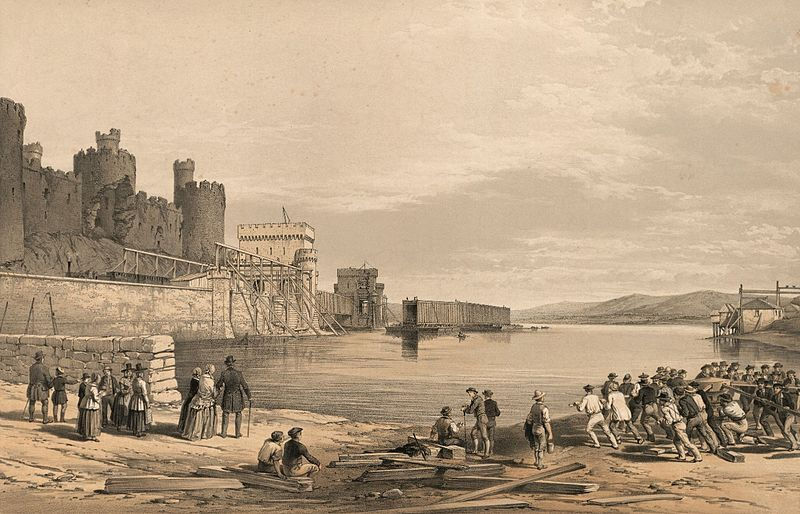
A lithograph entitled “Conway Bridge” showing the second wrought-iron box girder tube being floated into position, c. September 1848. Image used under Creative Commons licence.
The bridge contractor was William Evan. The ironwork was constructed by Easton & Amos.
On 15 June 1846, the foundation stone of the towers was laid. The towers accommodated entrance portals within twin arches, through which the railway are carried into the tubes. The tubes are made of 16mm riveted wrought iron with cellular roofs and bases, and sheeted sides; each one weighs roughly 1,320 tonnes. The tubes, which are 129.2 meters long and 4.4 meters wide, were constructed using shipbuilding techniques.
Once completed onshore, the tubes were attached to pontoons, floated along the river and jacked into position between the abutments; steam-powered hydraulic engines lifted the bridge elements into place.
On 6 March 1848, the first tube was floated; its installation took nine days to complete.
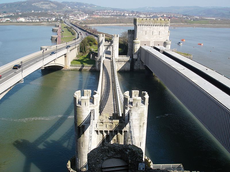
Thomas Telford’s Suspension Bridge above the River Conwy as seen from Conwy Castle, with the rail bridge to the right and the new road bridge to the left. Image by Bencherlite is used under Creative Commons licence.
Operational Life
The bridge was officially opened in 1849, although the first tube had been completed for traffic during April 1848. Stephenson wanted to test the structure, the first tubular crossing, to be sure it was capable of carrying the weight of a locomotive and its rolling stock. The testing was performed by Fairbairn and achieved favourable results. The bridge effectively endorsed the construction of the larger Britannia Bridge.
During 1899, the tubular sections were reinforced with cast iron columns to reduce the load on the span across the river to accommodate the increasingly heavy trains being used on the route. The bridge’s weight capacity had been exceeded according to a survey. The columns were fitted with inspection gantries to ease maintenance but during the 2000s they were deemed to be unnecessary and were removed.
Telford’s suspension bridge with the railway bridge to the right of it. Image by Mick Knapton is used under Creative Commons licence.
In September 1950, Conwy Tubular Bridge was recognized as being a Grade I listed structure; it is also a scheduled monument (CN167), protecting it as a historical asset for the nation. By the 21st century, the bridge is the only surviving example of a tubular bridge designed by Stephenson.
The original Britannia Bridge was damaged beyond repair by fire in 1970; it was rebuilt as a two-tier truss arch bridge made of steel and concrete. The bridge is maintained by Network Rail as a part of the British railway network. Its heritage is protected and actively managed by Cadw, the historic environment organisation of the Welsh Government.
Read more in
Wikipedia.
See also
Grace’s Guide
mywarrington is not responsible for external websites
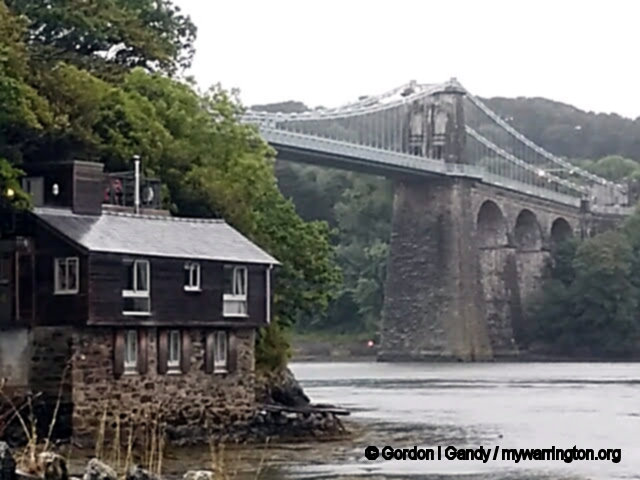
Britannia Bridge
Britannia Bridge (Welsh: Pont Britannia) is the rail bridge across the Menai Strait between the island of Anglesey and the mainland of Wales. It was originally designed and built by the noted railway engineer Robert Stephenson as a tubular bridge of wrought iron rectangular box-section spans for carrying rail traffic. Its importance was to form a critical link of the Chester and Holyhead Railway’s route, enabling trains to directly travel between London and the port of Holyhead, thus facilitating a sea link to Dublin, Ireland.
Decades prior to the building of the Britannia Bridge, the Menai Suspension Bridge had been completed, but this structure carried a road rather than track; there was no rail connection to Anglesey prior to its construction. After many years of deliberation and proposals, on 30 June 1845, a Parliamentary Bill covering the construction of the Britannia Bridge received royal assent. At the Admiralty’s insistence, the bridge elements were required to be relatively high in order to permit the passage of a fully rigged man-of-war. In order to meet the diverse requirements, Stephenson, the project’s chief engineer, performed in-depth studies on the concept of tubular bridges. For the detailed design of the structure’s girders, Stephenson gained the assistance of distinguished engineer William Fairbairn. On 10 April 1846, the foundation stone for the Britannia Bridge was laid. The construction method used for the riveted wrought iron tubes was derived from contemporary shipbuilding practices; the same technique as used for the Britannia Bridge was also used on the smaller Conwy Railway Bridge. On 5 March 1850, Stephenson himself fitted the last rivet of the structure, marking the bridge’s official completion.
Britannia Bridge. Image taken by Andrew Dixon from the Nelson memorial on the Menai Strait, Anglesey. Used under Creative Commons licence.
During March 1966, the Britannia Bridge received Grade II listed status.
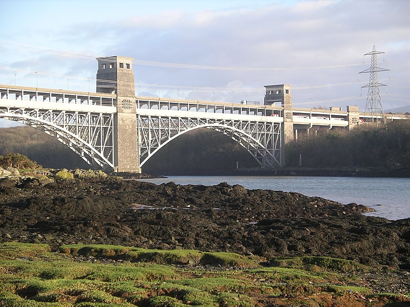
A disastrous fire in May 1970 caused extensive damage to the Britannia Bridge. Following investigation, it was determined that the damage to the tubes was so extensive that they were not realistically repairable. It was decided to rebuild the structure in a quite different configuration, reusing the piers while employing new arches to support not one but two decks, as the new Britannia Bridge was to function as a combined road-and-rail bridge. The rebuild process was performed in phases, being initially reopened in 1972 as a single-tier steel truss arch bridge, carrying only rail traffic. Over the next eight years more of the structure was replaced, allowing for more trains to run and a second tier to be completed. The second tier was opened to accommodate road traffic in 1980. The bridge was subject to a £4 million four-month in-depth maintenance programme during 2011. Since the 1990s, there has been talk of increasing road capacity over the Menai Strait, either by extending the road deck of the existing bridge or via the construction of a third bridge.
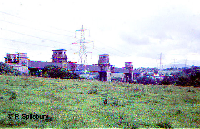
The original Britannia Bridge, destroyed by fire in 1970, when a group of youngsters Accidentally dropped their torch whilst exploring the tubes.
Photo © P. Spilsbury. Not available under Creative Commons.
Design
The opening of the Menai Bridge in 1826, one mile (1.6 km) to the east of where Britannia Bridge was later built, provided the first fixed road link between Anglesey and the mainland. The increasing popularity of rail travel shortly necessitated a second bridge to provide a direct rail link between London and the port of Holyhead, the Chester and Holyhead Railway. Other railway schemes were proposed, including one in 1838 to cross Thomas Telford’s existing Menai Bridge Railway pioneer George Stephenson was invited to comment on this proposal but stated his concern about re-using a single carriageway of the suspension bridge, as bridges of this type were unsuited to locomotive use. By 1840, a Treasury committee decided broadly in favour of Stephenson’s proposals, however, final consent to the route, including Britannia Bridge, would not be granted until 30 June 1845, the date on which the corresponding Parliamentary Bill received royal ascent. Around the same time, Stephenson’s son, Robert Stephenson, was appointed as chief engineer for the project.

Britannia Bridge Anglesey entrance. Image used under Creative Commons licence.
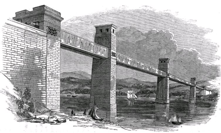
At the Admiralty’s insistence, any bridge would have to permit passage of the strait by a fully rigged ship. Stephenson therefore intended to cross the strait at a high level, over 100 ft (30 m), by a bridge with two main spans of 460-foot-long (140 m), rectangular iron tubes, each weighing 1,500 long tons (1,500 tonnes; 1,700 short tons), supported by masonry piers, the centre one of which was to be built on the Britannia Rock. Two additional spans of 230 ft (70 m) length would complete the bridge, making a 1,511-foot-long (461 m) continuous girder. The trains were to run inside the tubes (inside the box girders).
Britannia Bridge – circa 1852. Image used under Creative Commons licence.
For the detailed design of the girders, Stephenson secured the assistance of the distinguished engineer William Fairbairn, an old friend of his father and described by Stephenson as “well known for his thorough practical knowledge in such matters”. Fairbairn began a series of practical experiments on various tube shapes and enlisted the help of Eaton Hodgkinson “distinguished as the first scientific authority on the strength of iron beams” It became apparent from Fairbairn’s experiments that- without special precautions – the failure mode for the tube under load would be buckling of the top plate in compression, the theoretical analysis of which gave Hodgkinson some difficulty.
When Stephenson reported to the directors of the railway in February 1846, he attached reports by both Hodgkinson and Fairbairn. From his analysis of the resistance to buckling of tubes with single top plates, Hodgkinson believed that it would require an impracticably thick (and therefore heavy) top plate to make the tubes stiff enough to support their own weight, and advised auxiliary suspension from link chains.
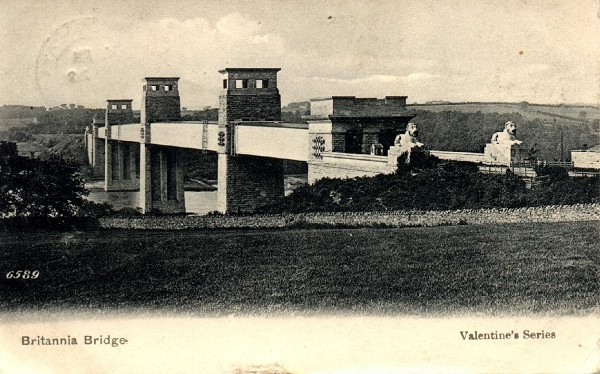
The old Britannia Bridge on a postcard from the private collection of Jochem Hollestelle.
Image used under Creative Commons licence.
Stephenson’s report drew attention to the difference of opinion between his experts, but reassured the directors that the design of the masonry piers allowed for the tubes to be given suspension support, and no view need yet be taken as to the need for it, which would be resolved by further experiments. A 75-foot (23 m) span model was constructed and tested at Fairbairn’s Millwall shipyard, and used as a basis for the final design. Stephenson, who had not previously attended any of Fairbairn’s experiments, was present at one involving this ‘model tube’, and consequently was persuaded that auxiliary chains were unnecessary. Although Stephenson had pressed for the tubes to be elliptical in section Fairbairn’s preferred rectangular selection. was adopted. Fairbairn was responsible both for the cellular construction of the top part of the tubes, and for developing the stiffening of the side panels. Each main span weighed roughly 1,830 tonnes.
On 10 April 1846, the foundation stone for the Britannia Bridge was laid, marking the official commencement of construction work at the site.
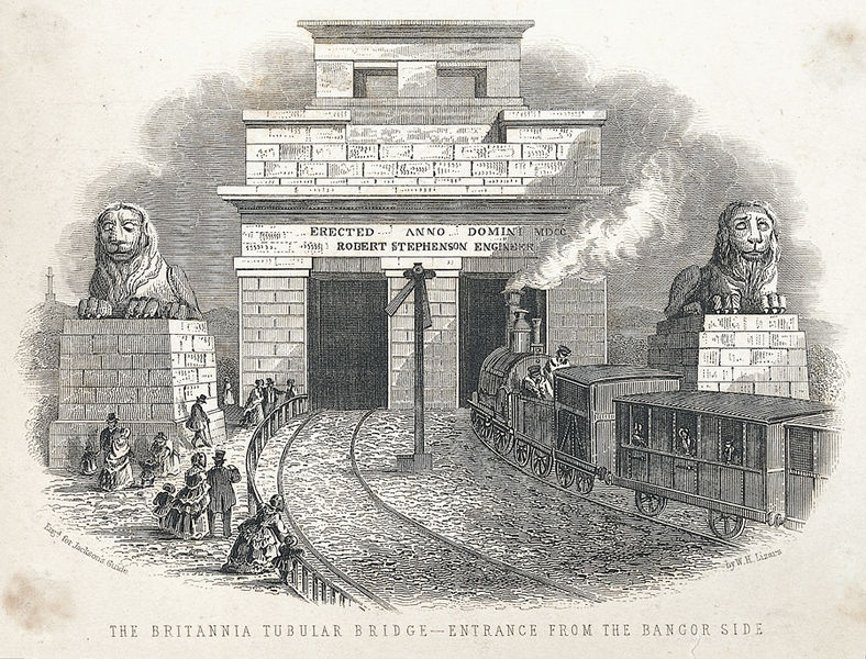
A view of the entrance to the Britannia Bridge from the Bangor side, showing a steam train entering the bridge, people watching, two large stone lions and an inscription relating to the engineer, Robert Stephenson. The scene is from around 1850. Image used under Creative Commons licence.
The resident engineer for the structure’s construction was civil engineer Edwin Clark, who had previously aided Stephenson in performing the complex structural stress calculations involved in its design process. The first major elements of the structure to be built were the side tubes, this work was performed in situ, using wooden platforms to support it. The construction method used for the iron tubes was derived from contemporary shipbuilding practices, being composed of riveted wrought iron plates 5⁄8 inch (16 mm) thick, complete with sheeted sides and cellular roofs and bases. The same technique as used for the Britannia Bridge was also used on the smaller Conwy Railway Bridge, which was built around the same time. On 10 August 1847, the first rivet was driven.
Working in parallel to the onsite construction process, the two central tube sections, which weighed 1,800 long tons (1,830 tonnes) apiece, were separately built on the nearby Caernarvon shoreline. Once they had been fully assembled, each of the central tubes was floated, one at a time, into the causeway and directly below the structure. The in-place sections were gradually raised into place using power hydraulic cylinders; they were only raised by a few inches at a time, after which supports would be built underneath the section to keep it in place. This aspect of the bridge’s construction was novel at the time. Reportedly, the innovative process had been responsible for costing Stephenson several nights of sleep at one stage of the project.
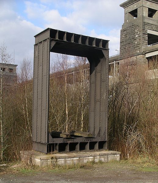
A section of the original wrought-iron tubular bridge standing beside the modern crossing.
Image by User:Velela is used under Creative Commons licence.
The work did not go smoothly; at one point, one of the tubes allegedly came close to being swept out to sea before being recaptured and finally pushed back into place. The tubes were maneuvered into place between June 1849 and February 1850.
On 5 March 1850, Stephenson himself fitted the last rivet of the structure, marking the bridge’s official completion. Altogether, the bridge had taken over three years to complete. On 18 March 1850, a single tube was opened to rail traffic. By 21 October of that year, both tubes had been opened to traffic.
For its time, the Britannia Bridge was a structure of “magnitude and singular novelty”, far surpassing in length both contemporary cast beam or plate girder iron bridges. The noted engineer Isambard Kingdom Brunel, a professional rival and personal friend of Stephenson’s, was claimed to have remarked to him: “If your bridge succeeds, then mine have all been magnificent failures”.
On 20 June 1849, Brunel and Stephenson had both looked on as the first of the bridge’s tubes was floated out on its pontoons. The construction techniques employed on the Britannia Bridge had obviously influenced Brunel as he later made use of the same method of floating bridge sections during the construction of the Royal Albert Bridge across the River Tamar at Saltash.
There was originally a railway station located on the east side of the bridge at the entrance to the tunnel, run by the Chester and Holyhead Railway company, which served local rail traffic in both directions.
However, this station was closed after only 8+1⁄2 years in operation owing to low passenger volumes. In the present day, little remains of this station, other than the remnants of the lower-level station building. A new station named Menai Bridge was opened shortly afterwards.
The Lions
The bridge was decorated by four large lions sculpted in limestone by John Thomas, two at either end. Each was constructed from 11 pieces of limestone. They are 25 ft (7.6 m) long, 12 ft (3.7 m) tall, and weigh 30 tons.
These were immortalized in the following Welsh rhyme by the bard John Evans (1826–1888), who was born in nearby Menai Bridge:
Pedwar llew tew
Heb ddim blew
Dau ‘ochr yma
A dau ‘ochr drew
Four fat lions
Without any hair
Two on this side
And two over there
The lions cannot be seen from the A55, which crosses the modern bridge on the same site, although they can be seen from trains on the North Wales Coast Line below.
The idea of raising them to road level has been suggested by local campaigners from time to time.
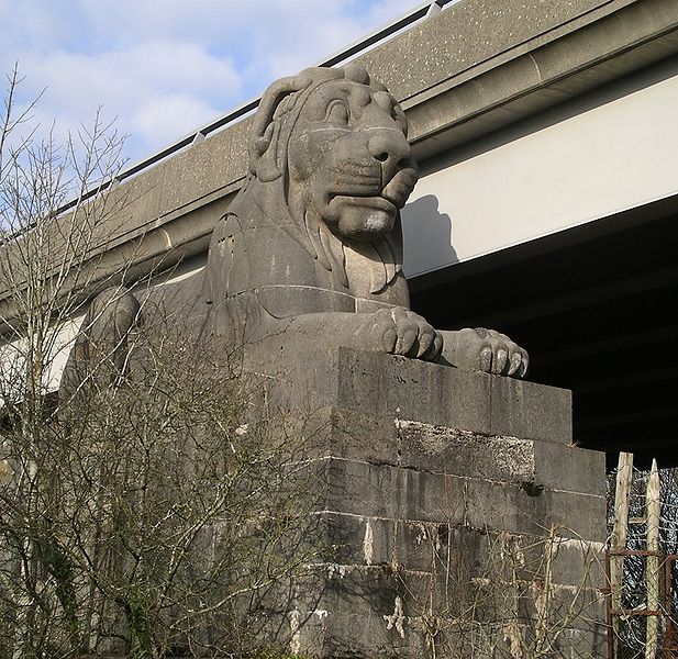
Britannia Bridge – monumental Lion statue. One of the 4 monumental sculptures of lions constructed to greet passengers travelling over the Britannia Bridge. View of these lions is now obscured by the road deck constructed after the 1970 fire.
Image by User:Velela is used under Creative Commons licence.
Fire and Reconstruction
During the evening of 23 May 1970, the bridge was heavily damaged when boys playing inside the structure dropped a burning torch, setting alight the tar-coated wooden roof of the tubes.
Despite the best efforts of the Caernarfonshire and Anglesey fire brigades, the bridge’s height, construction, and the lack of an adequate water supply meant they were unable to control the fire, which spread all the way across from the mainland to the Anglesey side.
After the fire had burned itself out, the bridge was still standing. However, the structural integrity of the iron tubes had been critically compromised by the intense heat; they had visibly split open at the three towers and had begun to sag. It was recognized that there was still danger of the structure collapsing. As a consequence, the bridge was rendered unusable without the enactment of major restorative work.
In light of events, the chief civil engineer of British Railways’ London Midland region, W.F. Beatty, sought structural advice from consulting engineering company Husband & Co. Following an in-depth investigation of the site performed by the company, it was determined that the cast iron beams inside the towers had suffered substantial cracking and tilting, meaning that the tubes required immediate support at all three towers.
The Royal Engineers were quickly brought in to save the bridge, rapidly deploying vertical Bailey bridge units to fill the original jacking slots in the masonry towers. By the end of July 1970, a total of eight Bailey bridge steel towers had been erected, each being capable of bearing a vertical load of around 200 tonnes. Further analysis showed that the wrought iron tubes had been too badly damaged to be retained.
In light of this discovery, it was decided to dismantle the tubes in favour of replacing them with a new deck at the same level as the original tracks. With the exception of the original stone substructure, the structure was completely rebuilt by Cleveland Bridge & Engineering Company.
The superstructure of the new bridge was to include two decks: a lower rail deck supported by steel arches and an upper deck constructed out of reinforced concrete, to carry a new road crossing over the strait. Concrete supports were built under the approach spans and steel archways constructed under the long spans on either side of the central Britannia Tower.
The two long spans are supported by arches, which had not been an option for the original structure as a result of the clearance needed for tall-masted vessels; modern navigational requirements require much less headroom.
The bridge was rebuilt in stages. The first stage was to erect the new steel arches under the two original wrought-iron tubes. The arches were completed, and single-line working was restored to the railway on 30 January 1972 by reusing one of the tubes.
The next stage was to dismantle and remove the other tube and replace it with a concrete deck for the other rail track. Then the single-line working was transferred to the new track (on the west side); this allowed the other tube to be removed and replaced with a concrete deck (which is used only for service access) by 1974.
Finally the upper road deck was installed and by July 1980, over 10 years after the fire, the new road crossing was completed, and formally opened by the Prince of Wales, carrying a single-carriageway section of the A5 road (now the A55).
For more read Wikipedia
See also Menai Heritage
mywarrington is not responsible for external websites.
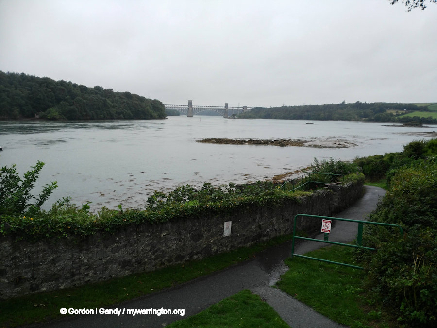
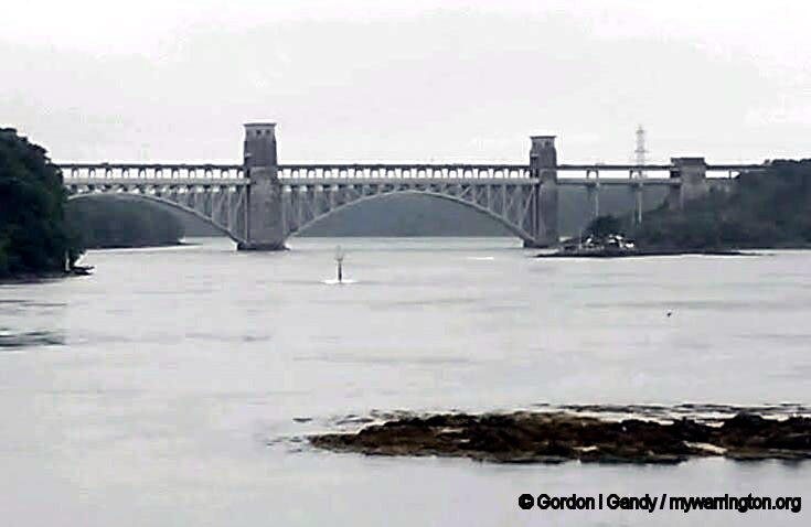
Two views of Britannia Bridge from below Menai Suspension Bridge in 2018 from my collection
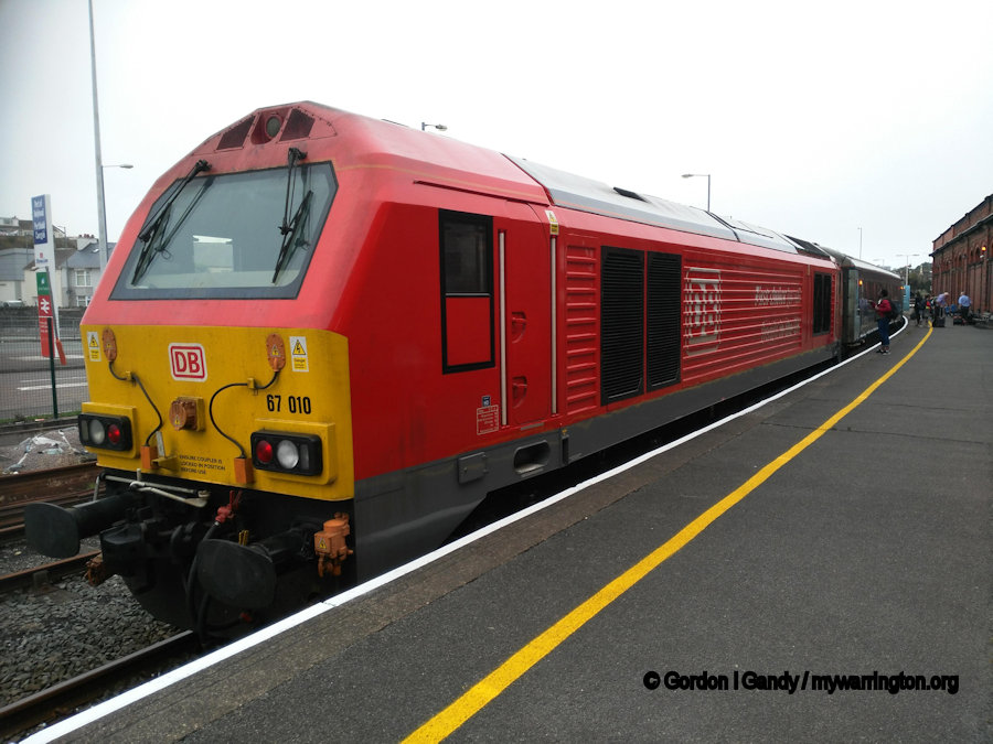
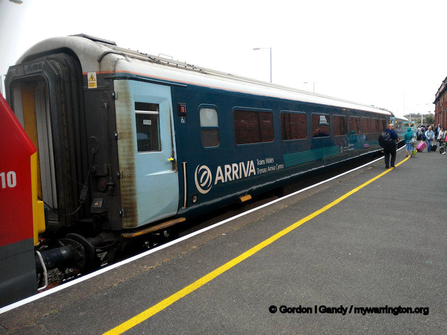
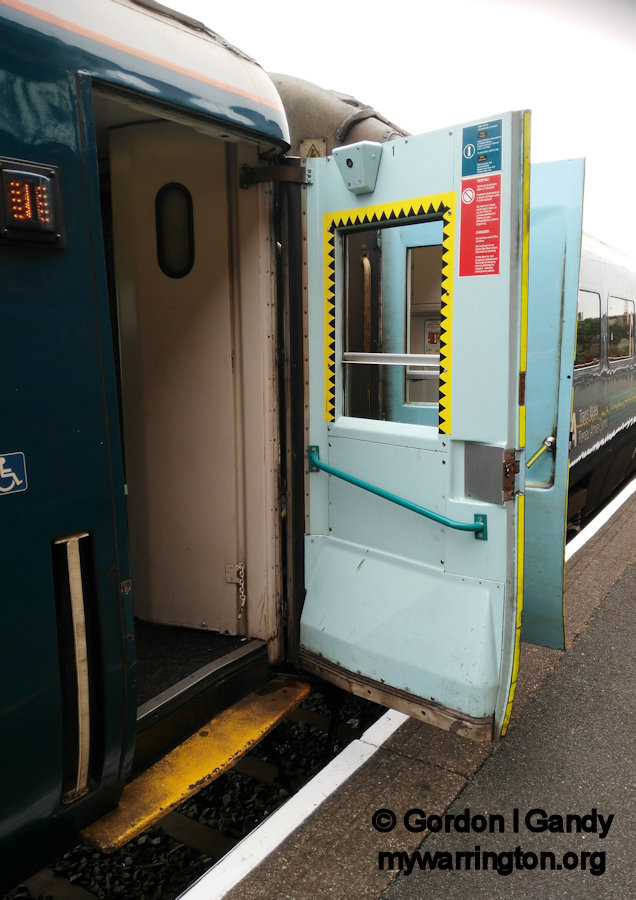
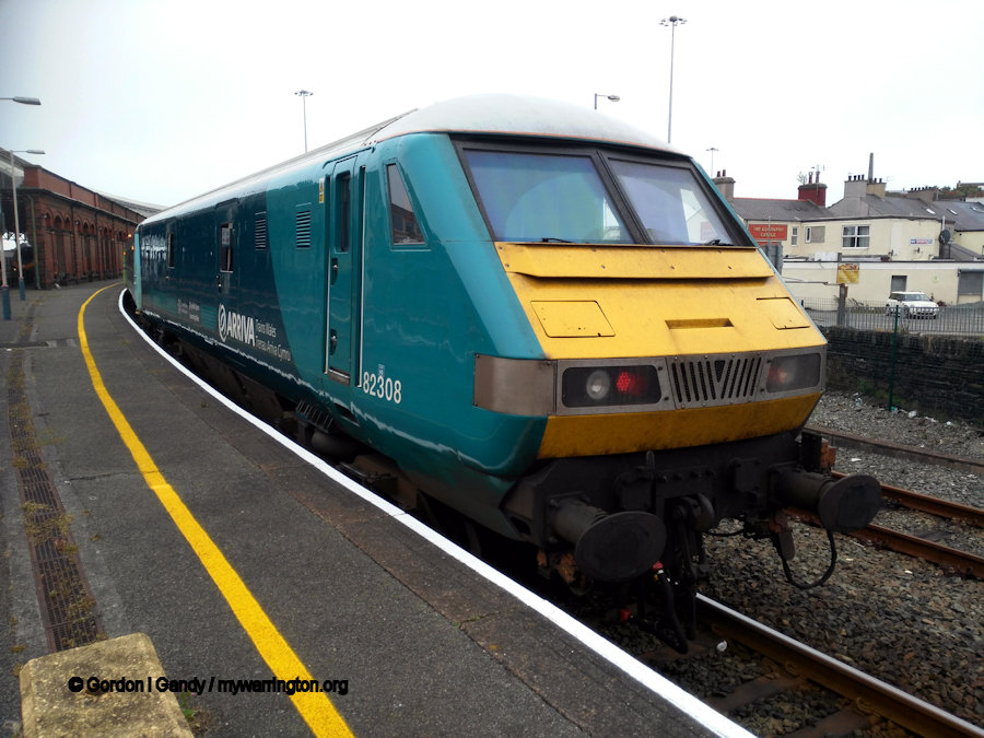
The train that took us to Holyhead on that same day in 2018. I thought slam door carriages had been discontinued,
but it was a nice bit of nostalgia to travel in one. It was pulled by a Class 67 locomotive with a Class 82 on the other end.
On the day we travelled to Trearddur Bay to bring back some memories of family holidays in the sixties and seventies.
We played on those rocks many a time. The caravan park was at the Cliffe Hotel, now Trearddur Bay Hotel.
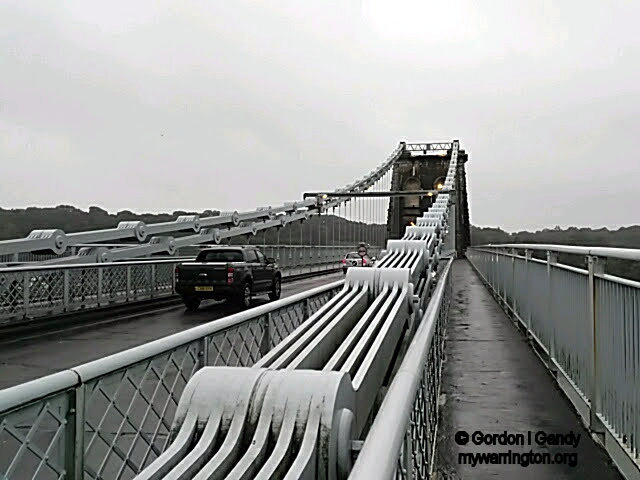
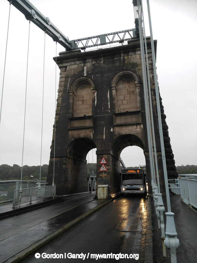
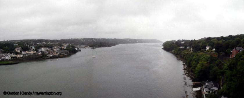
Views of Menai Suspension Bridge.
A view north from Menai Suspension Bridge, with Anglesey on the left separated from the mainland on the right. Before the bridge was built, the only way to cross was by boat. The tidal flow made it a very difficult journey.

.jpeg)